The Design of the Welded Ball Valve (Part Two)
On this page
1.4 Spheres
The pressure of urban heating systems and urban gas pipeline systems is generally less than 2.5MPa. For low-pressure spheres, 304 hollow spheres can be used. Take welded ball valves with DN1200 and PN25 as an example, the inner diameter of the sphere is 1166, the outer diameter 1740, and the wall thickness 35. After finite element analysis, the analysis of sphere displacement (Figure 4) and stress intensity (Figure 5) can meet the design requirements under the state of pressure.
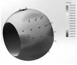
Figure 4 The analysis of the displacement of the sphere
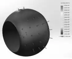
Figure 5 The analysis of stress intensity of the sphere
1.5 The anti blow out structure of the stem
The medium passes through the valve, the pressure in the middle cavity of the valve body may push the valve stem out. The valve stem and the medium are easy to rush out when the valve is disassembled, causing injury to personnel. To prevent this from happening, a boss anti blow out structure is designed at the lower end of the valve stem. In this way, even if the packing and thrust pad are burnt or damaged due to other reasons in the event of a fire, the medium pressure of the valve body will make the valve stem boss and the sealing surface of the valve body be in close contact, preventing a lot of media leaking from the damaged packing part.
1.6 Anti-static devices
When the valve is operated, electrostatic charge is generated and accumulated on the ball due to the friction between the ball and the valve seat made of non-metallic materials like teflon. In order to prevent the generation of static sparks, an anti-static device should be installed on the valve, and the electric charge accumulated on the sphere will be conducted through the static electricity between the sphere and the valve stem, or the valve stem and the valve body.
1.7 Actuating devices
Welded ball valves of a size less than or equal to DN150 are operated by handles, and those greater than or equal to DN200 adopt turbine operation. For welded ball valves operated by handles, when the ball valve is open, the direction of the wrench should be parallel to the ball channel. The handle or turbine operating device shall have a limit device.
2. Technical performance
Design and manufacture: according to GB/T12237 Steel Ball Valves for Petroleum, Petrochemical and Related Industries, JB/T12006-2014 Steel Welded Ball Valves, GB/T37827-2019 Welded Ball Valves for Urban Heating
Pressure tests: according to GB/T13927 Pressure Tests for Industrial Valves
Welding materials: in accordance with NB/T47018.1 to NB/T 47018.7 Technical Conditions for Ordering Welding Materials for Pressure-bearing Equipment
Welding procedure qualification: according to NB/T47014 Welding Procedure Qualification for Pressure-bearing Equipment
The welding procedures are based on NB/T47015 Welding Procedures for Pressure Vessels
The inspection of welding specimens: NB/T47016 Mechanical Properties Inspection of Welding Specimens for Pressure-bearing Equipment Products
Non-destructive testing: based on NB/T47013.1 to NB/T 47013.13 Non-destructive Testing of Pressure Equipment
Nominal diameters: DN15 to DN1600
Nominal pressure: PN25
Strength test pressure: 3.75MPa
Water seal test pressure: 2.75MPa
Air tightness test pressure: 0.6±0.1MPa
Applicable media: water and gas
Applicable temperatures: -29 to 150℃
The pressure of urban heating systems and urban gas pipeline systems is generally less than 2.5MPa. For low-pressure spheres, 304 hollow spheres can be used. Take welded ball valves with DN1200 and PN25 as an example, the inner diameter of the sphere is 1166, the outer diameter 1740, and the wall thickness 35. After finite element analysis, the analysis of sphere displacement (Figure 4) and stress intensity (Figure 5) can meet the design requirements under the state of pressure.
Figure 4 The analysis of the displacement of the sphere
Figure 5 The analysis of stress intensity of the sphere
1.5 The anti blow out structure of the stem
The medium passes through the valve, the pressure in the middle cavity of the valve body may push the valve stem out. The valve stem and the medium are easy to rush out when the valve is disassembled, causing injury to personnel. To prevent this from happening, a boss anti blow out structure is designed at the lower end of the valve stem. In this way, even if the packing and thrust pad are burnt or damaged due to other reasons in the event of a fire, the medium pressure of the valve body will make the valve stem boss and the sealing surface of the valve body be in close contact, preventing a lot of media leaking from the damaged packing part.
1.6 Anti-static devices
When the valve is operated, electrostatic charge is generated and accumulated on the ball due to the friction between the ball and the valve seat made of non-metallic materials like teflon. In order to prevent the generation of static sparks, an anti-static device should be installed on the valve, and the electric charge accumulated on the sphere will be conducted through the static electricity between the sphere and the valve stem, or the valve stem and the valve body.
1.7 Actuating devices
Welded ball valves of a size less than or equal to DN150 are operated by handles, and those greater than or equal to DN200 adopt turbine operation. For welded ball valves operated by handles, when the ball valve is open, the direction of the wrench should be parallel to the ball channel. The handle or turbine operating device shall have a limit device.
2. Technical performance
Design and manufacture: according to GB/T12237 Steel Ball Valves for Petroleum, Petrochemical and Related Industries, JB/T12006-2014 Steel Welded Ball Valves, GB/T37827-2019 Welded Ball Valves for Urban Heating
Pressure tests: according to GB/T13927 Pressure Tests for Industrial Valves
Welding materials: in accordance with NB/T47018.1 to NB/T 47018.7 Technical Conditions for Ordering Welding Materials for Pressure-bearing Equipment
Welding procedure qualification: according to NB/T47014 Welding Procedure Qualification for Pressure-bearing Equipment
The welding procedures are based on NB/T47015 Welding Procedures for Pressure Vessels
The inspection of welding specimens: NB/T47016 Mechanical Properties Inspection of Welding Specimens for Pressure-bearing Equipment Products
Non-destructive testing: based on NB/T47013.1 to NB/T 47013.13 Non-destructive Testing of Pressure Equipment
Nominal diameters: DN15 to DN1600
Nominal pressure: PN25
Strength test pressure: 3.75MPa
Water seal test pressure: 2.75MPa
Air tightness test pressure: 0.6±0.1MPa
Applicable media: water and gas
Applicable temperatures: -29 to 150℃
3. The selection of the material
Valve bodies: The valve body with small and medium diameters is made of 20 inches seamless steel pipes, and the large-diameter valve body is made of rolled Q235, Q345R steel plates.
Spheres: 304 hollow spheres, A105 plus ENP solid spheres
Stems: 20Cr13, AISI 4140 plus ENP
Seat: PTFE plus C, VITON AED
Springs: INCONEL X-750
4. Welding and stress relief treatment
The welding procedure qualification of the welding seam on the valve body shall comply with the standard of NB/T47104. The welding seam of the welded joint with the thickness of being less than or equal to 32mm on the valve body should be preheated to more than 100 degrees before welding and the welding joint whose thickness is less than or equal to 38mm does not need to be subjected to post welded heat treatment. The rest of the welding seam should be subjected to heat treatment for stress relief should be carried out according to requirements of GB/T150.4. When the thickness of the welded joint is greater than 32mm, the heat treatment is not carried out after welding or the welding stress cannot be relieved by heat treatment; the manufacturer shall provide an evaluation report of the welding seam without heat treatment after welding to prove its safe use.
5. Working principles
Welded ball valves are mainly composed of valve bodies, valve seats, balls, valve stems, handles, turbines, electric devices or other driving devices. The main function of the ball valve is to cut off or connect the fluid channel in the pipeline. Therefore, the action principle of the ball valve is very simple: a certain torque is applied to the upper end of the valve stem with the help of a handle, turbine or other driving devices and transmitted to the ball to make it rotate 90 degrees; the through hole of the ball coincides with or is perpendicular to the centerline of the valve body channel, the ball valve is fully opened or fully closed.
6. Conclusion
Steel pipe welded ball valves have simple structure, energy conservation and emission reduction, long service life and no maintenance, and can be widely used in urban heating systems and urban gas pipeline engineering.