The Key Processes of Super Large Butterfly Valves
On this page
1. Controlling deformation of super large weldments
One of the difficulties in the manufacture of super-large welded butterfly valves is the control of the welding deformation of the valve body and butterfly plate. Excessive welding deformation will seriously affect the quality and performance of the super large butterfly valve, making it difficult to guarantee the quality of the subsequent processes. The welding process of the super-large butterfly valve requires strict control of roundness and coaxiality of the shaft hole of the valve body. The main methods of controlling deformation are introduced below.
1.1 Reasonable structural design
The valve body and butterfly plate are designed with axial symmetry and center symmetry, which can theoretically minimize the influence of deformation caused by welding.
1.2 The application of the rigid fixation method in the group welding process
The valve body and butterfly plate are large welded structural parts. The rigid fixation method is adopted. After forming, welding is applied to increase the rigidity or restraint intensity of the welded parts to achieve the purpose of reducing deformation.
1.3 The application of the inverse deformation method in the welding process
According to the deformation law of the group weldment, make it deformed in the opposite direction before welding to offset the deformation after welding (Figure 1).
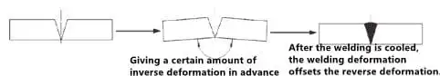
Figure 1 The inverse deformation method
1.4 The application of the heat balance method in the group welding process
The root cause of deformation caused by welding is uneven heating. Since the welding seam of the butterfly plate is all on one side of the main plate, the butterfly plate will be curled and deformed perpendicular to the center line of the shaft hole after welding. Therefore, before the last two symmetrical cover plates are welded, it is necessary to adopt the heat balance method. Select two unconstrained lines as heating straightening lines. After cooling, check the unevenness of the main plate until it is within the allowable tolerance range. Finally, the two symmetrical cover plates are welded (Figure 2).
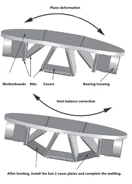
Figure 2 The heat balance method
1.5 The integral annealing treatment of welded parts
The main purpose of post-weld heat treatment is to improve the performance of the welding area, eliminate welding residual stress, stabilize the size of the weldment and improve the processing technology. Key parameters such as annealing temperatures and holding time should be strictly controlled during the overall annealing of welded parts.
The material of the valve body and disc belongs to the Fe-1, and the annealing parameters are formulated according to the NB/T47015-2011 Welding Regulations for Pressure Vessels post-weld heat treatment process.
The formula for calculating the shortest holding time is as follows:
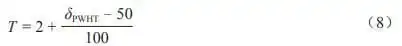
In the formula, T is the shortest holding time, and is the thickness of the workpiece after welding heat treatment (mm). Post-weld heat treatment thickness of the valve body is 120 mm; post-weld heat treatment thickness of the disc is 100 mm. After calculation, the shortest holding time of the valve body is 2.7 hours, and the shortest holding time of the disc is 2.5 hours. The actual minimum holding temperature is 600°C, and the holding time is 6 hours.
2. Surfacing welding ER309 stainless steel wire of the 40Cr valve shaft
The base material for surfacing welding is 40Cr, which has poor weldability and is prone to cracks. ER309 is austenitic stainless steel welding material, and improper control of welding process parameters, interlayer thickness and weld bead width will cause hot cracks. In order to ensure the quality of surfacing welding of 40Cr valve shaft, special surfacing equipment for valve shafts was developed (Figure 3). The welding current (160 to 190A) is strictly controlled; the thickness of the surfacing layer is adjusted to be less than and equal to 3mm and the width of the weld bead 5mm to achieve uniform rotation and uninterrupted welding, beautiful welding seams along the circumference, stable and reliable welding quality. Penetration testing was performed on the surfacing surface after welding, and no welding defects such as cracks and lack of fusion were found.
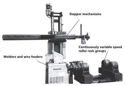
Figure 3 Special surfacing equipment for valve shafts
3. Conclusion
The design and manufacture of this electric butterfly valve with large diameters conform to GB/T 13927-2008 Pressure Tests for Industrial Valves and requirements of the contract. Various performance verification tests were carried out according to the standard specifications and the requirements of the contract. The results showed that there is no leakage in the forward and reverse directions, and the shaft seal didn't leak. The strength test of the valve body and the valve showed no permanent deformation and structural damage. The action test was flexible. The time of opening and closing the valve meets the requirements. The butterfly valve has reasonable design, advanced technology, reliable sealing and excellent performance, good technical and economic effects and industry influence.
One of the difficulties in the manufacture of super-large welded butterfly valves is the control of the welding deformation of the valve body and butterfly plate. Excessive welding deformation will seriously affect the quality and performance of the super large butterfly valve, making it difficult to guarantee the quality of the subsequent processes. The welding process of the super-large butterfly valve requires strict control of roundness and coaxiality of the shaft hole of the valve body. The main methods of controlling deformation are introduced below.
1.1 Reasonable structural design
The valve body and butterfly plate are designed with axial symmetry and center symmetry, which can theoretically minimize the influence of deformation caused by welding.
1.2 The application of the rigid fixation method in the group welding process
The valve body and butterfly plate are large welded structural parts. The rigid fixation method is adopted. After forming, welding is applied to increase the rigidity or restraint intensity of the welded parts to achieve the purpose of reducing deformation.
1.3 The application of the inverse deformation method in the welding process
According to the deformation law of the group weldment, make it deformed in the opposite direction before welding to offset the deformation after welding (Figure 1).
Figure 1 The inverse deformation method
1.4 The application of the heat balance method in the group welding process
The root cause of deformation caused by welding is uneven heating. Since the welding seam of the butterfly plate is all on one side of the main plate, the butterfly plate will be curled and deformed perpendicular to the center line of the shaft hole after welding. Therefore, before the last two symmetrical cover plates are welded, it is necessary to adopt the heat balance method. Select two unconstrained lines as heating straightening lines. After cooling, check the unevenness of the main plate until it is within the allowable tolerance range. Finally, the two symmetrical cover plates are welded (Figure 2).
Figure 2 The heat balance method
1.5 The integral annealing treatment of welded parts
The main purpose of post-weld heat treatment is to improve the performance of the welding area, eliminate welding residual stress, stabilize the size of the weldment and improve the processing technology. Key parameters such as annealing temperatures and holding time should be strictly controlled during the overall annealing of welded parts.
The material of the valve body and disc belongs to the Fe-1, and the annealing parameters are formulated according to the NB/T47015-2011 Welding Regulations for Pressure Vessels post-weld heat treatment process.
The formula for calculating the shortest holding time is as follows:
In the formula, T is the shortest holding time, and
2. Surfacing welding ER309 stainless steel wire of the 40Cr valve shaft
The base material for surfacing welding is 40Cr, which has poor weldability and is prone to cracks. ER309 is austenitic stainless steel welding material, and improper control of welding process parameters, interlayer thickness and weld bead width will cause hot cracks. In order to ensure the quality of surfacing welding of 40Cr valve shaft, special surfacing equipment for valve shafts was developed (Figure 3). The welding current (160 to 190A) is strictly controlled; the thickness of the surfacing layer is adjusted to be less than and equal to 3mm and the width of the weld bead 5mm to achieve uniform rotation and uninterrupted welding, beautiful welding seams along the circumference, stable and reliable welding quality. Penetration testing was performed on the surfacing surface after welding, and no welding defects such as cracks and lack of fusion were found.
Figure 3 Special surfacing equipment for valve shafts
3. Conclusion
The design and manufacture of this electric butterfly valve with large diameters conform to GB/T 13927-2008 Pressure Tests for Industrial Valves and requirements of the contract. Various performance verification tests were carried out according to the standard specifications and the requirements of the contract. The results showed that there is no leakage in the forward and reverse directions, and the shaft seal didn't leak. The strength test of the valve body and the valve showed no permanent deformation and structural damage. The action test was flexible. The time of opening and closing the valve meets the requirements. The butterfly valve has reasonable design, advanced technology, reliable sealing and excellent performance, good technical and economic effects and industry influence.